Introducing...
"HERMIT"
...another 5-motor walker!
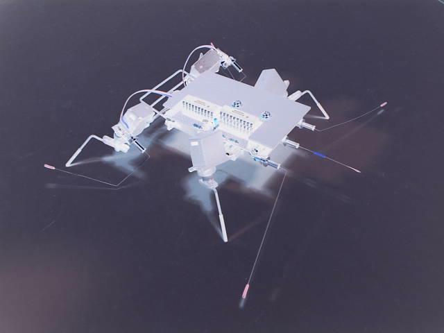
"the smaller the bot, the better it looks"
Introduction:
Yes, I know guys, I've made "again" another Walkman-style bot. Not so surprising, but this is what I really love to build.........ever since! ;-)
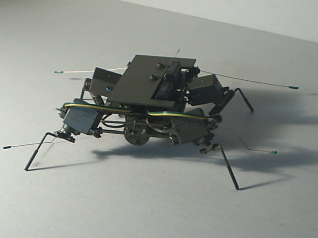
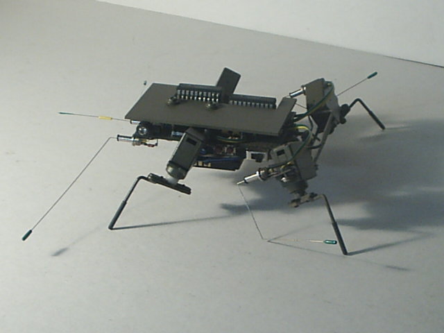
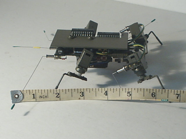
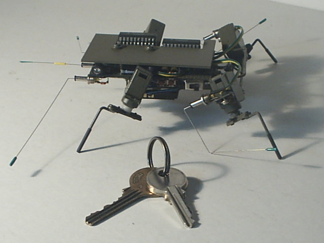
This is my newest and latest robotic creature, named Hermit. Hermit is a 5-motor walker (Walkman based circuitry), and was again inspired from Mark Tilden's unique design, named VBug Walkman 1.5. This little bot can do all the behavior that Walkman does. The coolest part (for me) of this bot is that, it can do the "crabwalk" steps, when either left or right tactile is hit. You'll see the video clips later on. Another thing is, this bot was carefully designed and constructed, and it's compact and lowered. I guess this is much smaller/shorter than the real Walkman. Don't you think?
Anyway, I hope you'll like this little bot and all the contents on this page. I'll just see you guys in the BEAM group anytime ok? Take care guys and have fun! Enjoy the rest of the page!
Specs, materials and features:
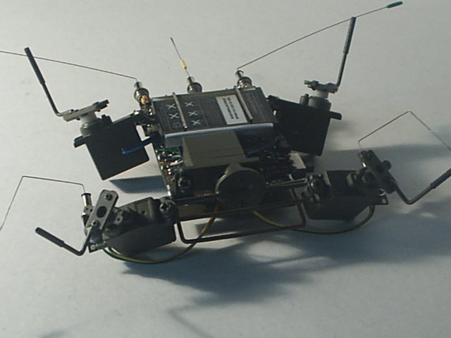
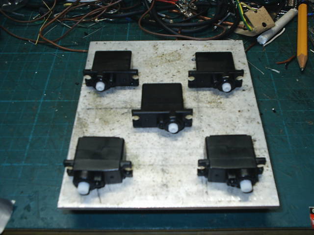
- 5 hobby micro servos (removed the electronics but the mechanical stop inside the gear box remains)
- guitar strings (tactile sensors)
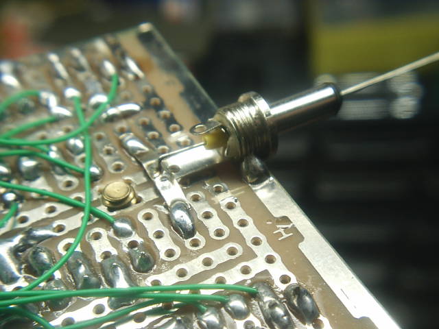
- small barrel plugs (tactile sensors)
- uses IR LEDs as eyes (phototaxis)
- crabwalking, reversing, reversing and turning (phototaxis), hind leg lifting and phototropic
- powered by 3.6 volts Li-Polymer cellphone battery at 900mA
- paper clips and solid copper wires construction (body frames and brackets)
- spray painted
- heat-shrink tubings (legs, etc.)
- pieces of tin cans, pcb's and small nuts and bolts (servo mountings)
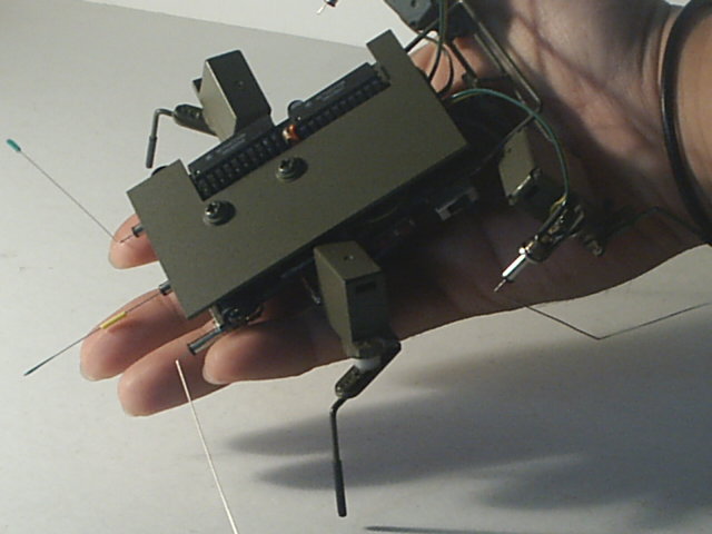
Overall dimensions:
- Length : 5 inches (including legs)
- Width : 6 inches (including legs - legs are spread out)
- Height : 1.8 inches (including the stacked IC's)
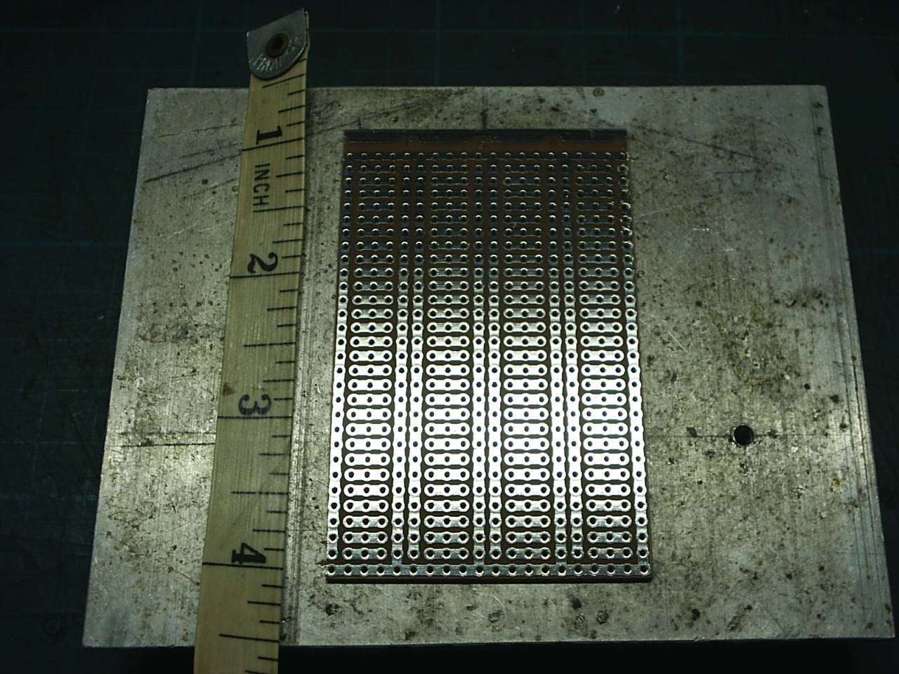
PCB dimensions:
- Length : 3.4 inches
- Width : 2 inches
- Height : a little bit lower than half an inch
PICS
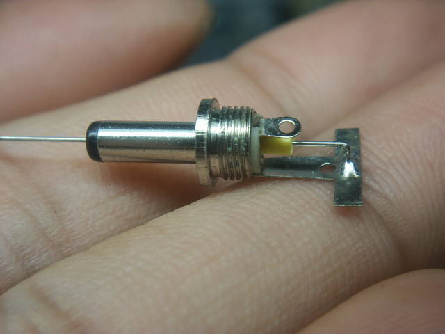
Using a multi/universal battery charger
(usually used for mobile phone batteries)
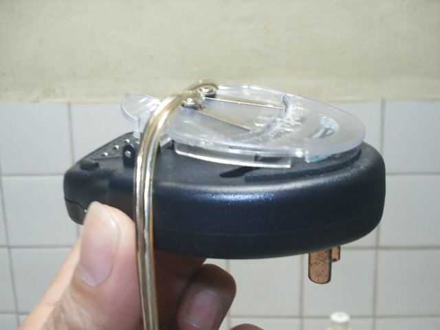
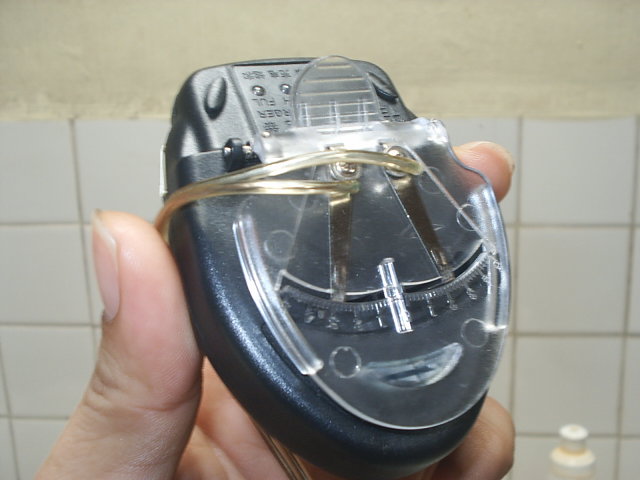
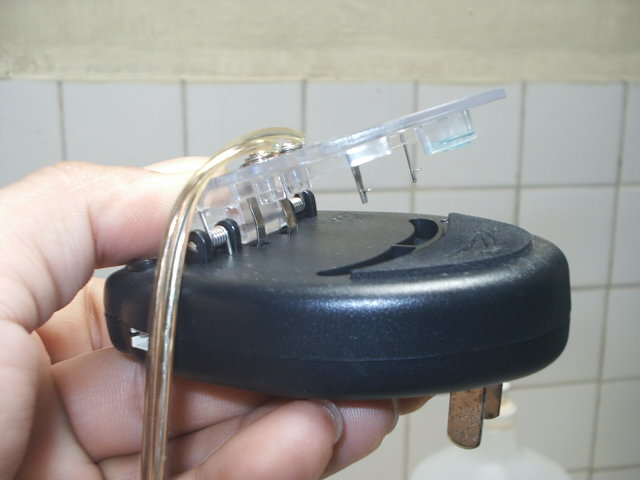
2 terminal leads as seen inside the battery clip (+ & - contacts).
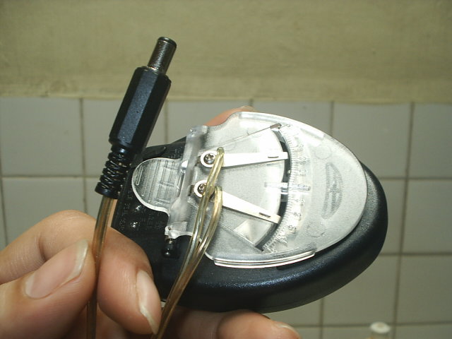
I placed a barrel plug with a long wire, screwed on the + & - terminals of the charger.
Newer images added!


Schematic Diagram
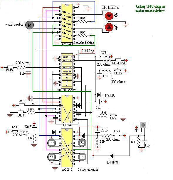
The only difference in this schematic is, I've used 74AC240 chip instead of 74**241. You can see some minor changes in the waist motor driver circuit. Both me and a friend of mine (Ralph Ca�as) thought about this and there it goes, it worked!
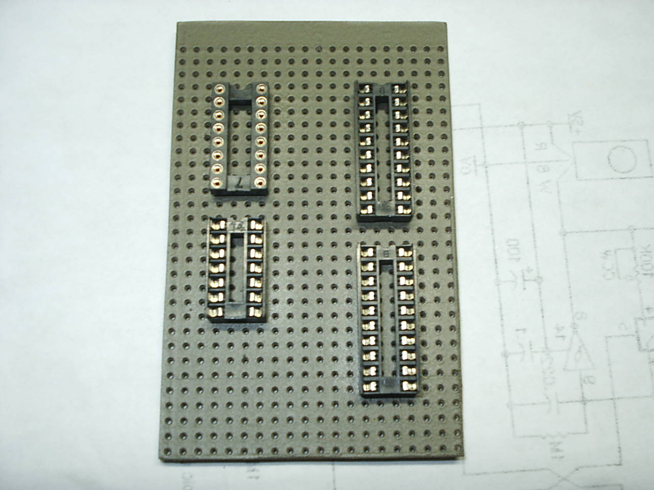
And also, just add another photodiode on the left side, just like on the right side of the motor driver. Experiment with different resistor values for Nv's 1, 2, 3 & 4 on the 18-pin IC socket.
Video Clips
(sorry for the video quality and the file size)
- crabwalk 2.36MB
- leglift 2.26MB
- phototaxis 1.07MB
- phototropic 2.28MB
- just playing with hermit 5.69MB
- playing with it - video 1 28MB (NEWLY ADDED!)
- playing with it - video 2 16.3MB (NEWLY ADDED!)
- playing with it - video 3 10.8MB (NEWLY ADDED!)
- playing with it - video 4 25.9MB (NEWLY ADDED!)
Copyright � 2005 by Harold R. Ilano
hetfield9999@yahoo.com
All Rights Reserved.
BEAM Patents by Mark W. Tilden.
Visitors since Dec. 23, 2005