
" Rovore "
- the smart Bicore Tank photovore -
(using only 1 DPDT relay to switch from photophobic to phototropic)
started Aug.7, 2006

Introduction:
This bot is just a "bicore tank" with some add-on circuits to make it avoid light (full) and seek light (hungry). Rovore's circuits are just simple to build, effective and tested by me. I've also did lots of experimentation on what kind of circuit to be used as a controller for this bot. My plan was just to build a simple way to make this bot photophobic first (full charge) and phototropic when it gets hungry (low batt.) and stops at the brightest light to charge its batteries for several minutes and off it goes again (fully charged) to get away from the light. I've used only 1 DPDT relay as the switching method for the bicore tank's photodiodes (eyes). I've also used large paper clips for stand-offs, # 1 guitar strings for the tactile sensors, mini barrel plugs for the tactile sensors and pieces of PCB as its body coverings, etc. Anyways, this bot uses 5-volt relay switches on every add-on circuits and a 3.6 volts cell phone battery (slim type). Ok let's go now to the next section.
Rovore's behavior:
When fully charged, this bot is in photophobic mode (avoids light). This way, it continues roaming around in the darkness or shadows. This behavior may take a while until its batteries becomes weak or low in voltage. This low-voltage thing makes Rovore phototropic (seek and follow the light source) and starts the beeper warning. When the light source is not bright enough, it won't stop there (for charging its batteries) and still continues searching for the brightest light (depending on the sensitivity settings on the dark-activated switch). As soon as it gets to the brightest light (high-wattage bulb or the sun), it will stop there and starts to charge its batteries for a while, or until it reaches 4 volts. Proper timing (capacitor) for the Time Delay Circuit is required (we'll be discussing this in a short while). When this bot is now fully charged, it starts or move again and avoids light, going to a darker place and the cycle repeats. You can even add more sensors for this bot, like putting heat sensors, so that when it gets to a hotter place, it back-up and gets away from there or even a moisture/wet sensors. An ultrasonic sensor for obstacle avoidance can also be used instead of tactile switches.
Circuit Operation:
Well, Rovore's circuit operation is just simple. When you switch it ON (ex. when fully charged), the bot will get away from any source of light. It will just roam around in dark corners or areas. This behavior is called "photophobic" or afraid of light. But when the bot's battery becomes low (about 3.6 volts), you'll hear a beeping sound as a warning, and now in "phototropic" mode or light-seeking. As soon as the bot reaches the bright light (high-wattage light bulb or sun), it will stop automatically right on that spot and begins charging its batteries by means of its solar panel on top of it. This solar-battery charging will take a while of about an hour or two, depending on the timer circuit, which uses a large capacitor value. When that time has elapse, the bot could be fully charged. The full charging depends on how bright and strong the light is, so if the light is not that bright and the timer is done, the bot's battery could still be low or not enough, and the bot will stay phototropic and searches the light again. Anyway, you'll notice that this bot still needs re-charging when you still hear the beeping sound.
The 1st circuit is basically a bicore tank. This controls the movement of the bot including the left and right tactile sensors and its eyes.
The 2nd circuit is the low-voltage alarm that triggers a relay switch whenever it detects low in battery voltage set by the 10k trimpot. This trimpot will be set according to what voltage you use for the battery and what voltage will be used for the zener diode. For example, when you use a 4.8 volts battery for your bot, and you want to set the trigger to 4 volts, use a 3.9 or even a 4.1 volts zener diode. This way, when the battery reaches 3.9 or 4.1 volts, the low-voltage alarm will trigger its relay (output), indicating low in voltage and it's now in phototropic mode. This relay switching has a connection with the bot's LDR's or photodiodes (left and right eyes) from the bicore tank. You can refer to the whole schematic of this bot below afterwards.
The 3rd circuit is a dark-activated relay. This means that when the bot detects a shadow or no light on its sensor (LDR or photodiode), the bot will still run and active (moving). This circuit is used to stop the bot from moving to conserve battery power when in solar charging (phototropic). It will also turn OFF all the circuit except the 4th circuit (timer). However, if the bot is in photophobic mode (afraid of light), the bot could still move away from the light source and it will not stop, even though the dark-activated relay is still at rest (normally-close). And when the bot got away from the light, the dark-activated relay will be in normally-open (ON), which releases its contact to solar charging (the bot is active). At the same time, the Timer relay will have no voltage (positive) connection anymore. Please refer to the whole schematic (wirings) to get my point.
While the 4th circuit is just an automatic turn ON relay timer. It is used when the bot needs more time to charge its battery. You can change the time setting as short or as long as you want by changing the capacitor value. This means that, the higher the value is, the longer the time it will take for charging (the bot is at rest). this circuit is also used to give a positive connection to the bot (like a power switch) to make the bot active. Like what I've mentioned earlier, the relays of the the dark-activated and timer circuits will swap, meaning the other is OFF and the other one is ON and vice-versa.....well, something like that, whew!
Well, I guess the schematic diagrams are easy to understand, right? If not, just let me know, but I'm sure anyone will help. And by the way, I'm sure that Wilf has also more and better ideas to make all of these as simple as possible. Wilf? :-D
NEW!!! ADDITIONAL INFORMATIONS:
I will just show you how the circuit works especially all the relay switching when the bot is in photophobic, phototropic and while charging. Please notice the encircled objects in green and the notes in red. Here we go...
(click to enlarge)

Photophobic mode

Phototropic mode

Charging mode

Fig. 1
Full-charged / (notice the relays of the dark-activated circuit and the timer circuit)

Fig. 2
Full-charged / (notice the relays of the dark-activated circuit and the timer circuit)
Circuits used:
1. Bicore Tank - robot controller
2. Low-Voltage Alarm (simple ones may also work) - use one "DPDT" 5-volts relay (to the output)
3. Dark-Activated Switch - use one "SPDT" 5-volts relay (to the output)
4. Automatic Turn-ON Relay switch - use one "SPDT" 5-volts relay (to the output)
5. 3.6 volts cell phone battery (900mA) - (4.1 volts fully charged)
6. One solar panel (from solar garden light) - 3.5 to 4.2 volts output
7. Simple edge sensors
8. LM3909 flasher circuit - used as a beeper
Schematic Diagrams
1st Circuit
Bicore Tank
2nd Circuit
Low-Voltage Alarm
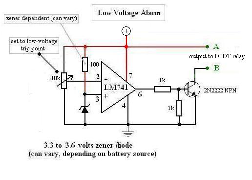
Here's how to calibrate this circuit:
- use an LED or a buzzer first (example) as the output signal connected to the relay
- apply a voltage source that's equal to the "would be battery" trip voltage. Ex: Zener = 3.3 volts, while battery = 3.x volts
- adjust the 10k pot until the LED or the buzzer turns ON
- remove the low voltage battery (3.x volts) and attach the fresh or fully charged 4.8 or 5 volts to the circuit
- the LED or the buzzer should turn OFF
- the LED or buzzer will turn ON again to indicate "low power"
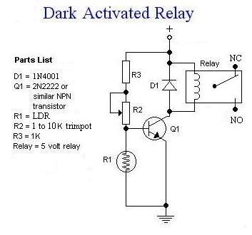
3rd Circuit
Dark-Activated Relay Switch
4th Circuit
Delayed Turn-ON Relay (Timer Switch)

The original circuit and its explanations can be found here.
Complete Schematic

click to enlarge
Here's a simple "edge sensor" circuit used by Rovore
(tested and it works!!!)

In this circuit, I've used tiny or small infrared LEDs and photodiodes. Just attach the 2 red points with the 1N4148 diodes shown above to pins 2 and 10 of the L293D bicore tank circuit. Just alter the two wirings if necessary. And also, make sure that when you mount these pairs of sensors, it must be faced down with a distance of about 1/4 inch or a little bit more from the floor or surface. So when it detects a black surface or especially an edge, the bot "should" and will avoid that edge (ex. a table or stair). You can see some pics of it below.
Note: Make sure the polarities of the IR LEDs and the photodiodes are correct, or else it won't work.
And here's a simple and common flasher using LM3909

I've used a piezo beeper instead of L.E.D., used to indicate if the battery is low (phototropic mode).
PICS
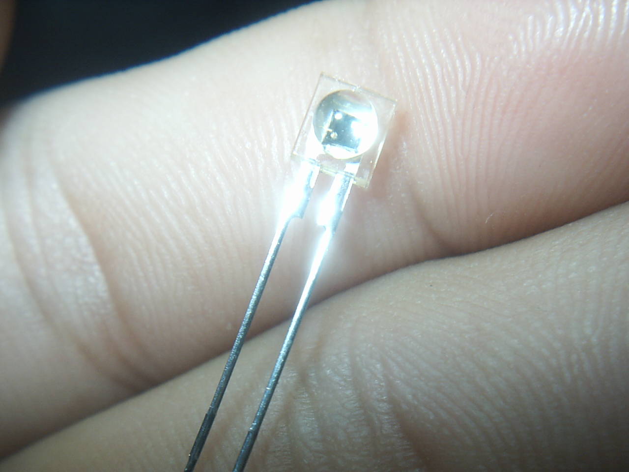
This is the phototransistor I've used as Rovore's eyes. I got this from a VCR. This one is very efficient to use, I recommend it.
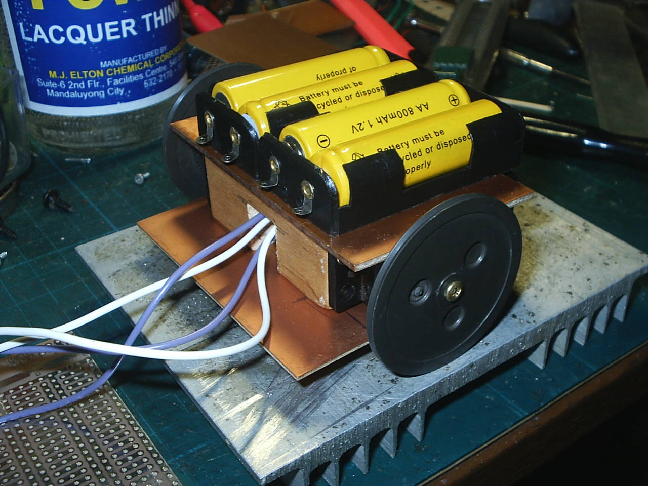
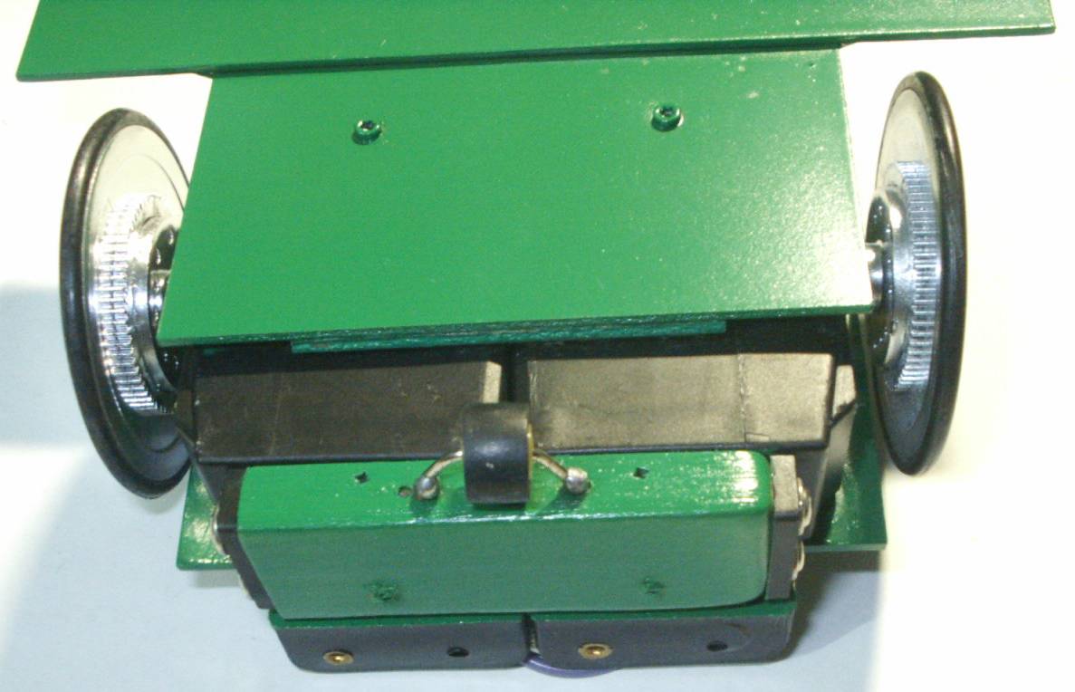
Yep, made of PCB's and some fine woods, etc. The wheels are from an old car stereo (thank goodness there were 2 of these inside, whew!).
Update : I replaced these batteries with a cell phone battery which is at 3.6 volts and 900mA, very light and slim type.
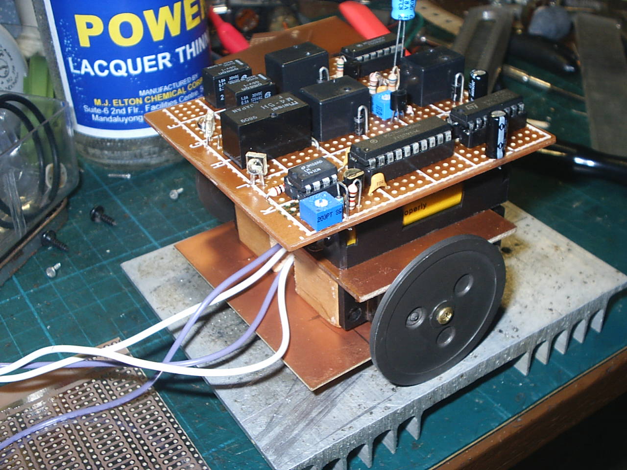
Testing...1...2...3...

Partially assembled and spray painted.
Another view.
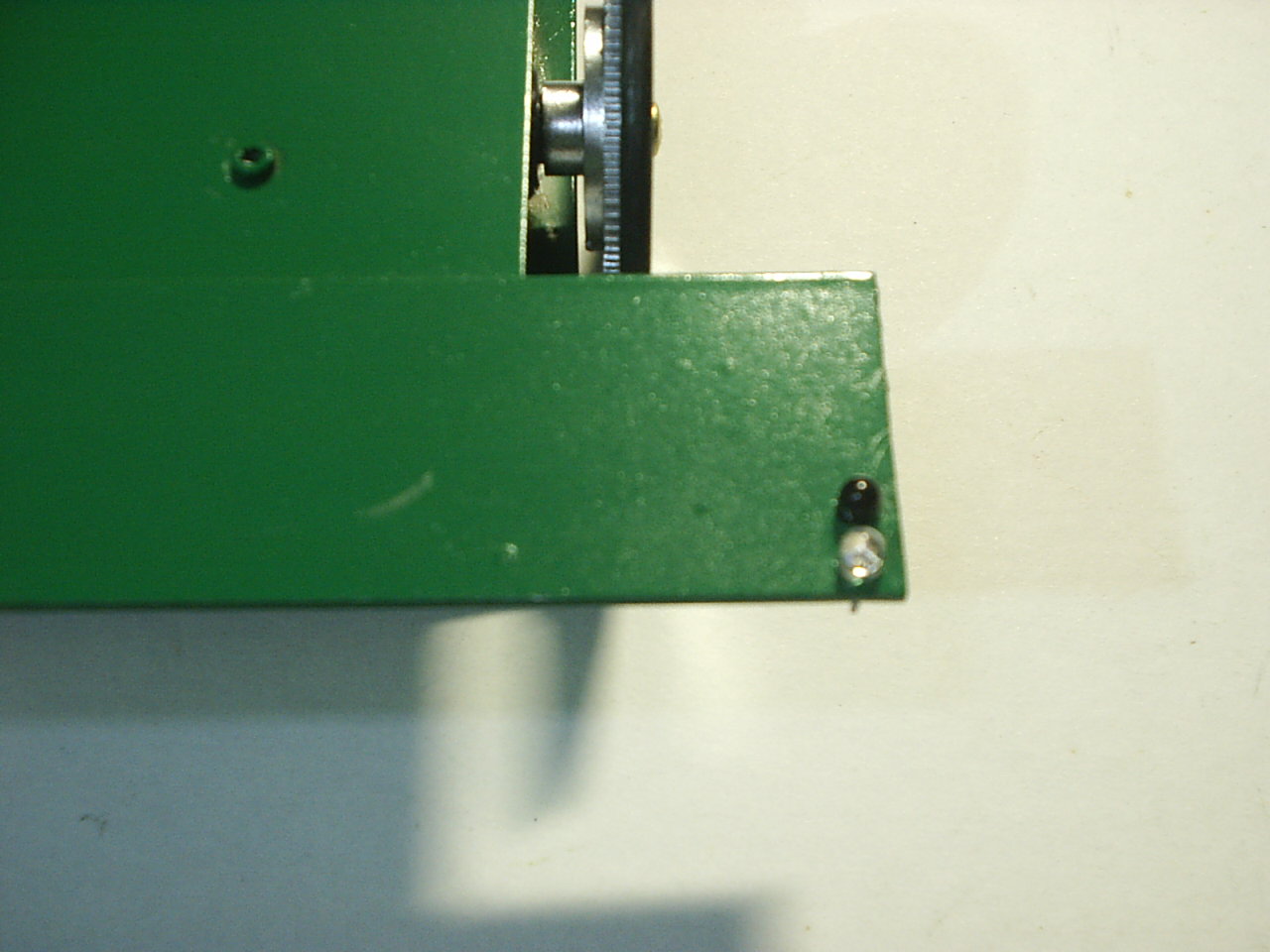
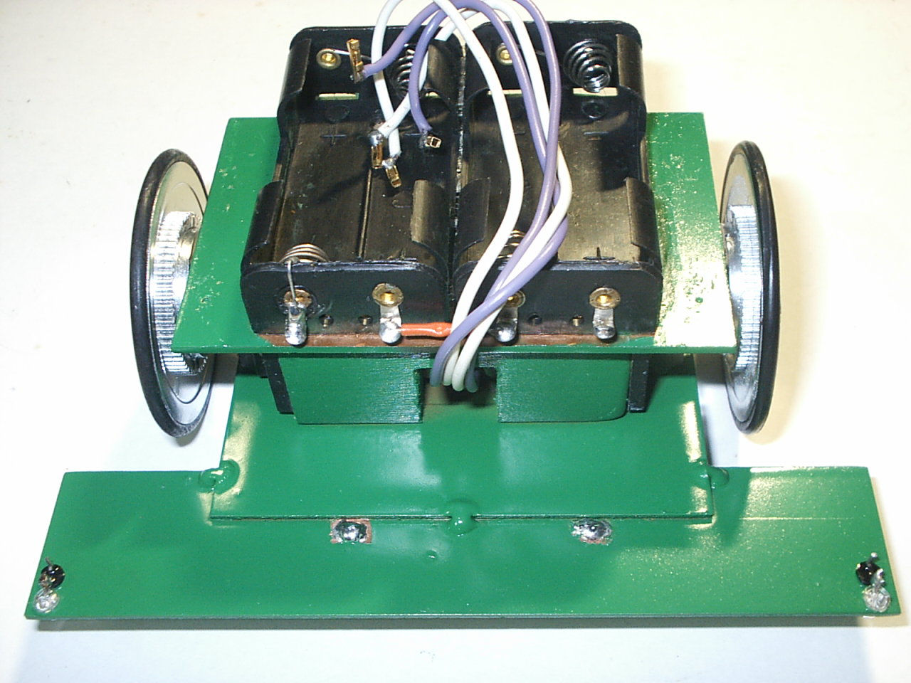
Drilled the PCB and inserted the small IR pairs for edge detection.
The 3rd wheel is from a cassette player with a paper clip.

Here it is...
More Pics
(Finished product but some modifications maybe added later on)
(click to enlarge)


New! Additional Pics
(just click to enlarge)


Video Clips
New ! Fully-charged Rovore video 1
New ! Fully-charged Rovore video 2
The last 2 video clips of Rovore (New!), shows that this bot has just finished its charging through a 100 watts desk lamp after 2 hours and a few minutes at 3.9 to 4 volts. After that amount of time, it moves again and avoids the light source (which Rovore used to charge its battery pack), and goes towards the dark place. This behavior is now in photophobic mode.
Important notes:
The solar panel's voltage must be 1 to 2 volts higher than the bot's battery pack. The current of the solar panel can be as high as you want, so the charging of the battery will be faster. It also depends on how strong the light source would be. The timing capacitor from the timer circuit can vary. It means that, if you want the bot to charge for a longer period of time, use a larger capacitor value. Experiment and observe, to get good results. And make sure, you take down notes or document your work every time.
'Hope you enjoy Rovore. See you again next time. Happy BEAMing guys!
Special thanks to : Dave H. from Solarbotics (for the web space), Wilf Rigter and Tony van Roon. And also, to my best friend, Arvin Camp. And to those people I haven't mention, thank you so much! To my visitors here, many thanks guys! I'll just see you all in the Yahoo group BEAM lists. ;-D
Copyright � 2006 by Harold R. Ilano. All Rights Reserved.
Any comment/s? question/s? suggestion/s? idea/s?
E-mail me : hetfield9999@yahoo.com
BEAM Patents by Mark W. Tilden
Visitors since Sept. 22, 2006