" T R O O P E R "
B.E.A.M. Robotics
Introduction:
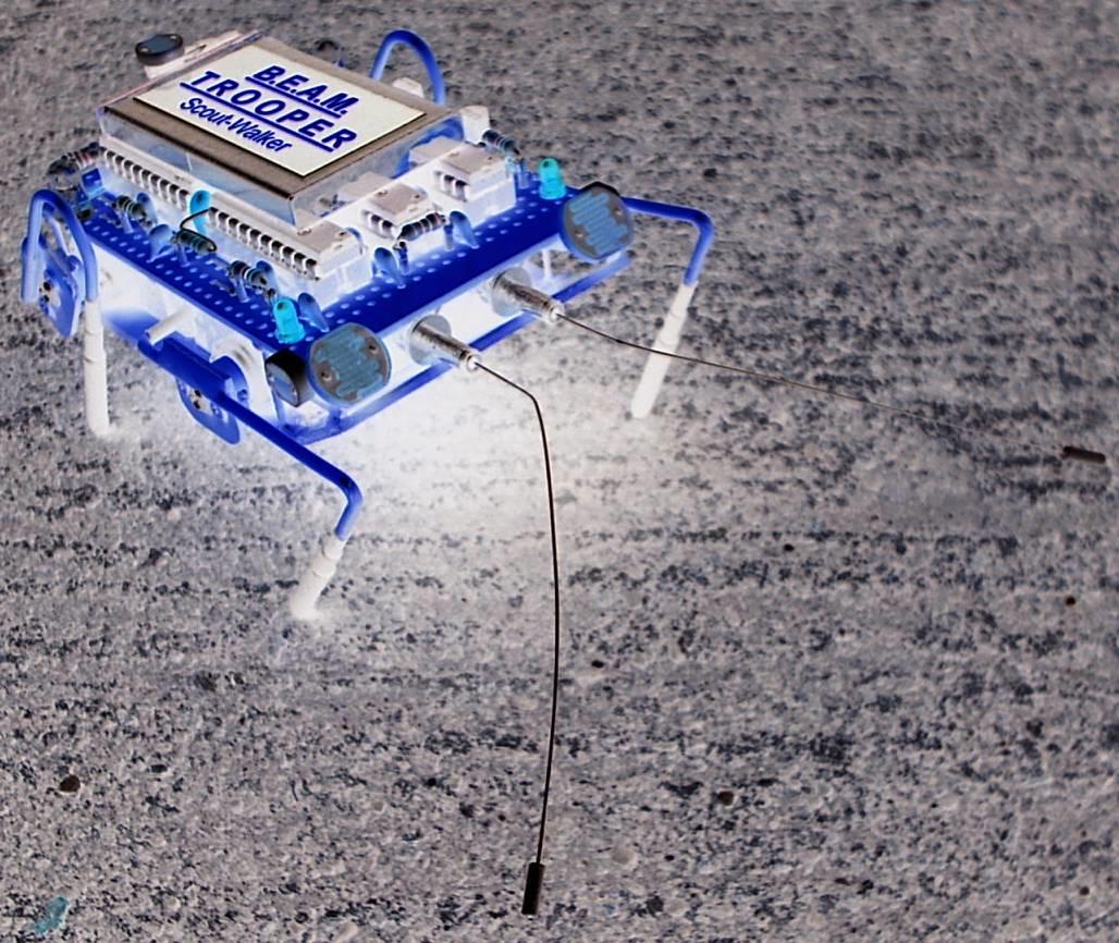
Trooper is a miniaturized Scout Walker 2 robot, as seen on Solarbotics site. It's a 4-motor walker design, constructed from pieces of PCB's and large paper clips. The behavior of this bot is actually the same as the original but I did some additional features to it. I just added 3 little and simple circuits.
This walker is phototropic. If it sees a bright light, it will go towards it and just walks from that spot, then stops in a few seconds then starts walking again. When Trooper pauses or stops, the 2 LED's turns ON, showing a multi-colored bright light on its back, just like a firefly or some sort. After a few seconds, it will start to go around the spot of light again and repeats the process, stop and go...stop and go...
If there are no light on Trooper (dark area), it will disable or turn OFF its phototropic feature and continues to walk, bumping on things, turn's left and right and reverses, as long as its battery pack has enough power to run him. Trooper has also a built-in "low- voltage monitor". If its battery pack goes low in charge, a visible red LED blinks, located at the rear side. A small piezo beeper can also be attached instead of blinking LED, but my piezo beeper is a little bit large that can't fit anywhere on it. So, I've used a blinker instead, as a visible warning.
I've built Trooper's circuit board just last year, I guess it was October 2006. I didn't finish it because of lack of time and I was always out. I began working with it last February this year, 2007. And now, it's finally done! It just feels great....yeah!
Schematic Diagrams

The diagram above, if you would recall, is the same as the original Scoutwalker 2 walker from Solarbotics. It's just a basic schematic without my additional circuits. I just made some modifications including resistor values. The resistor values shown above can be changed, depending on what motors are used and the battery voltage. 3.6 volts to 5 volts works fine. Just connect the enable lines from each motor drivers to the 1K resistor (center top IC). And also, connect the other end of the diode to any circuits you like (headbot, beeper, chirper, pummer or a multi-colored ultra-bright LED/s. This diode outputs a ground or negative signal. This is OFF when the bot is walking (negative signal does not flow). This is ON (negative signal flows) if the bot stops from walking. You can adjust how long it walks and how long it pauses, by changing the resistor values on pin 8 or pin 11. However, proper walking and how speed it walks can be adjusted by increasing or decreasing the master and slave resistor values. And of course, by changing the angles of each leg. You can also increase the value of the CC or "corpus colossum" resistor (I've used 5 Meg). Experiment!
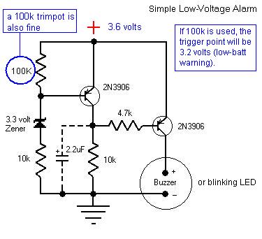
This diagram is a simple low-voltage indicator circuit. I just found this circuit a long time ago, on the internet that was used for R/C planes. Thanks to the guy who did this. Well, I just made some modifications again with this circuit. I've used a 100k resistor so that, the trigger point would be at 3.2 volts, if you use a 3.6 volts battery pack. It it triggers, a buzzer or a blinking LED will be ON, as a warning. So few components, you can actually free-form it, just what I did, and put it in a heat-shrink tubing for protection. And also, just connect the + and - terminals to the battery with a switch.
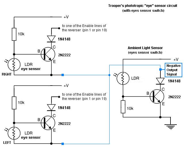
This last diagram are the light sensors, used by Trooper. The left and right eye sensors makes "him" phototropic (attracted to light). While the separate LDR sensor (at the right) is used for switching the phototropic feature ON or OFF, depending on light situations. The reason I made this was, if the bot doesn't have this "ambient light sensor" circuit, and if there's no light on "him" or in his area, this bot just reverses or walks backwards. The left and right eye sensors are just to trigger the reverser circuit (like a tactile switch) if there's no light to both or either eyes. In other words, the "eye sensor" circuits are just a simple dark-activated switch. While the "ambient light sensor" circuit is just a simple light-activated switch. Simple isn't it?
When you switch ON this bot, either it walks "or" pauses while flashing its 2 multi-colored LED's (whichever comes first). If there's light on the "ambient light sensor", no negative signal flows at the collector pin of the 2N2222 and through a diode. But if there's no light on the said sensor, negative signal flows to its collector pin and through the diode. Thus, triggering the reverser circuit, making the bot turn towards light or reverses.
Images


Pics from early stages...


.jpg)
.jpg)


Video Clips
These 2 video clips were recorded in "a little bit" low resolution video camera, to reduce large file size.
 7.41 MB (without audio)
 10.1 MB (with audio)
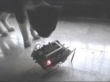 8.27 MB (with audio...and a kitten)
...more to come eventually!
About Trooper:
Well, about the parts, the parts are easy to find. I've used jumbo paper clips for the legs and medium paper clips for the stand-offs, to elevate the pcb on the micro servos. All the wirings were done underneath the pcb. A little bit confusing sometimes, but I'm used to it. I've used heat-shrink tubing for the feet and for traction. The tactile sensors are just mini barrel plugs and very thin guitar strings that was stretched out and soldered to it. The battery is a cell phone battery pack rated at 3.6 volts @ 850mA, not bad at all! The low-voltage monitor was free-formed and was inserted in a heat-shrink tubing that was also hidden inside and between the pcb and the servos. Also, the ambient light sensor was also free-formed and mounted behind the battery pack. This is used so that, when no light is present on this bot, it just continues to walk, looking for its way in any direction. 5 LDR's were used for the eyes and the ambient light sensor. The 2 clear ultra-bright LED's located near behind it are the multi-colored blinking LED's (like a Christmas lights or a pummer).
Behaviors / features:
When you first start Trooper (ON), it walks straight ahead (being phototropic). And when the area is bright, it just stays there, going around it. After walking for a few seconds, Trooper will stop and blinks its multi-colored ultra-bright LED's (left and right). It's so nice to watch it in the dark. After the lights flashes for a few seconds, it will resume to walk, searching for a bright light. But if there is no light on Trooper, the phototropic feature will be disabled. So, Trooper will just just roam around every corner, every obstacle on its way and turns left or right or even reverses when its tactile sensor/s is hit. And when its battery pack goes low (about 3.2 volts), a blinking red LED at the rear side will be ON. So you'll know when to charge "him". I added 3 circuits on this Scoutwalker-type bot because, first I don't need to use a head on it, instead, I just used LDR's as its eyes. Secondly, I've used a separate LDR for ambient light sensing. I thought about using this because, if this bot don't see any light or if it's in a dark area, this bot will always backs up or reverses (walking backwards, if no light is present). Until it sees and reaches a light source, that's just the time to walk forward, left or right. Quite boring isn't it? So, that's why 2 light-activated switching circuits were used (left and right eyes). And 3rd, I've added a low-voltage monitor. Well, you know what this is. I thought about putting a solar panel on him, but it will just make him taller or a little bit bigger or wider. I really planned to make Trooper as small as possible with additional features in it (modifications), which turned out quite well.
A few more information and details might or will be added here eventually. But for now, I'm working on Trooper's video clips and I'll let you know when it's done. You could e-mail me for some comments anytime. And I would like to thank Solarbotics for giving me this space and everything else. Thanks a lot Dave Hrynkiw!!!
LASIK Denver:
Building bots is a lot of fun but can take time and patience because of all the various size parts and pieces you will be working with. Having healthy vision is essential for working with robotics and small parts. Bot builders who have complications with their vision or eyes often seek out advice from vison corrections centers like LASIK Denver. Vision treatment options that LASIK Denver provide can help get a bot builder who has had eye complications back to doing what they love best.
E-mail me at : hetfield9999@yahoo.com
Copyright 2007 by : Harold R. Ilano
B.E.A.M. Patents by : Mark W. Tilden
- All Rights Reserved -
Visitors since March 14, 2007